The hierarchy of protection measures against falls from heights must be respected at all times, that is:
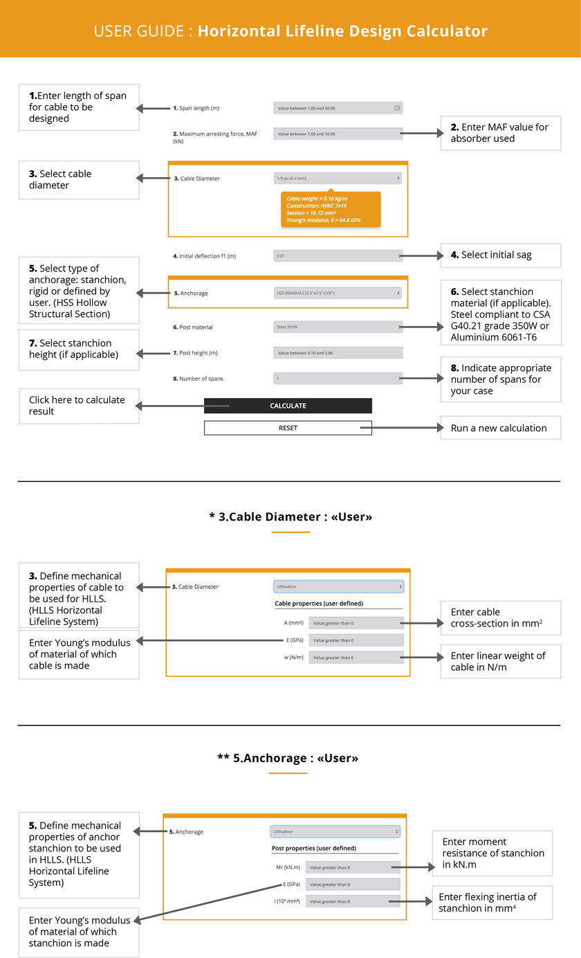
Personal protection systems against falls from heights consist of several components, including a harness, a lanyard equipped with an energy absorber, connection accessories (carabiners, shackles, etc.) and anchoring connectors. To give workers greater freedom of movement, a horizontal lifeline system (HLLS) can be used. HLLSs are an inexpensive, effective way to protect workers against falls from heights.
Under section 2.10.15 of the Safety Code for the Construction Industry (S-2.1, r. 4), the anchoring points of personal protection systems against falls from heights must have a minimum resistance or be designed by an engineer in compliance with CAN/CSA Standard Z259.16, Design of Active Fall Protection Systems.
The Web-based calculation tool should not under any circumstances whatsoever be used as a substitute for the work of an engineer having expertise in protection against falls from heights. Only people with the appropriate knowledge and experience are qualified to use it.
The analytical calculation method used in the software tool is based on the following assumptions:
The Web-based calculation tool has been validated solely for metal cables and is not to be used for synthetic-cable HLLSs.
Disclaimer: The authors assume no responsibility for the use that may be made of any component of the website Horizontal Lifeline System Design and the webpages referenced therein.
This tool has no legal or regulatory value. It is provided as an aid for engineers specializing in fall protection and for OHS officers and horizontal lifeline system (HLLS) users who wish to assess whether their HLLS installations are compliant. This tool is not a substitute for the opinion of a qualified engineer and must be used with caution. Only people with the appropriate knowledge and experience are qualified to use it.
Under section 2.10.15 of the Safety Code for the Construction Industry (S2.1, r. 4):
The fall arrest connecting device of a safety harness must be secured to:
(2) a flexible continuous anchorage system (horizontal life line) with one of the following characteristics:
The hierarchy of control measures (elimination of hazard at source, collective protection measures, personal protective equipment) must be respected at all times.
This tool is not to be used to design an HLLS in the following cases:
Before launching the tool, users should refer to the section Scope and Limitations. It is also recommended that they read the Terms and conditions of the IRSST website, as well as the research report associated with the development of this Web based tool.